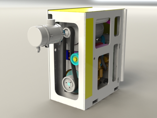
Custom Designed Automated Vision Inspection System for the Automotive Manufacturing Industry

An automotive Tier 1 manufacturing client approached MJ Engineering to design and install a custom automated vision based part inspection system. The specific need was to verify that each model is assembled in the correct orientation. The inspection system allows the operator to place a part for inspection upon completing the previous task. The inspection system has a color touch screen operator interface panel for selecting the model to be run and to display pass fail status of the inspection

The vision system is programmed to look for specific characteristics. The system verifies these characteristics are present where they belong and also verify none are present where they don’t. By doing so it is capable of providing 100% verification of the specified characteristics. Each passing part is automatically marked with a quick dry ink for quality tracking purposes.

The customer had been using manual inspection of each part which was very time consuming and also made it difficult to maintain the zero error requirements their customer requires.

Project Description

This automated vision based inspection station verifies the correct assembly of every part manufactured.

Capabilities Applied/Processes

Cell Design

  • Conception of cell that meets unique production requirements.
  • Create SolidWorks© 3D models of cell concept
  • Vision and lighting application concept and testing

Installation

Start-Up

Operator and Maintenance Training

Features/Benefits

Features

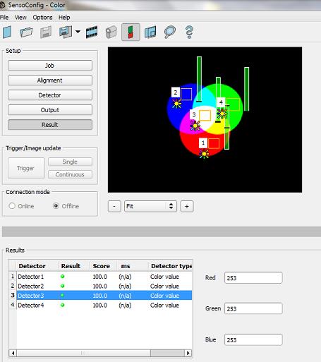
  • Utilizes Teledyne Dalsa BOA color vision/li>
  • Portable Cell/li>
  • Provides visual and audible feedback on each part inspected./li>
  • Capable of 30+ individual inspections per part./li>
  • Multiple part types can be programmed and inspected.

Benefits

  • By utilizing a color vision system and the correct lighting for the application it is able to compensate for color and finish variances that are not critical to the part quality test./li>
  • Multiple parts can be programmed and accessed directly by the integrated operator HMI./li>
  • Easily modified to meet new product requirements.

More Info

Overall Cell Dimensions
Table top unit: 39” High x 39” Wide x 39” Deep

Pattern Size Capabilities
50mm high by 300mm wide

Tightest Tolerances
1mm

Material Used
Glass beads

In Process Testing Performed
Samples of all models were provided for initial concept testing

Industry for Use
Automotive

Delivery Location
Ohio

Standards Met
Customer supplied part models

Product Name
Vision Based Automated Inspection System

Integration of Diesel Motor within a Shuttle Car for the Mining Industry

MJ Engineering was tasked with integrating a diesel motor and electric generator in place of a battery pack or cable reel of a mining shuttle car. The customer, who provided a specific set of specifications, needed the diesel motor packaged within the shuttle car’s existing 55 ¾” x 68″ x 32 ¾” reel compartment. We also faced the added challenge of having to ensure that the new motor/generator system was easy to maintain in the harsh and unforgiving mine environment.

To accomplish these tasks, MJ Engineering used a number of different design and engineering processes. We first designed a proper motor/generator mounting frame. Using the natural frequency of the motor/generator we were able to determine which frequencies to avoid so we could design the most stable mounting frame. Then we focused on designing a drive system linking the motor to the generator. Utilizing our outstanding design team we were able to eliminate the need for a battery pack or cable reel within the mining shuttle car. After all this work was completed, MJ Engineering was able to supply the client with 3D CAD models and CAD drawings of the final design.

To learn more about our outstanding design work on this project please contact MJ Engineering or see below for details.

Project Description

MJ Engineering was tasked with integrating a Diesel Motor and an Electric Generator in a mining Shuttle car.

Capabilities Applied/Processes

Design/Engineering

  • Design Concept for Various Motor/Generator Mounting Frames
  • Designed drive system linking Motor to Generator
  • Used the Natural Frequency of Motor/Generator to Determine the Natural Frequency to Avoid When Designing Mounting Frame
  • Created SolidWorks and Solid Edge 3D CAD Models & CAD Drawings of Final Design for Manufacturing

Features/Benefits

Process Requirements

  • Package Motor/Generator within Existing Reel Compartment
  • Ensure it is Easy to Maintain in a Mine environment.
  • Use Motor/Generator System Provided by Client

Benefits

  • Eliminates the need for a Cable

More Info

Overall Dimensions
Car: 352″long x 108″ wide x 93 ½” high Motor/Generator Compartment: 55 ¾ wide x 68 high x 32 ¾” deep

Material Used
Steel plate and tubing

Industry for Use
Mining
Mineral

Delivery Location
Canada

Standards Met
Customer supplied specifications

Product Name
Integration of Diesel Motor/Electric Generator into Mining Car