Backlight Conveyor

Conveyor Width (in.) Conveyor Load (lbs.) Backlight Width (in.)
5 80 3.5
6 90 4.5
8 100 6.5
10 120 8.5
12 120 10.5
18 120 16.5
21 120 19.5

Project Description

The MJ Engineering Backlight Conveyor is a modified conveyor that possesses ULTRA-BRIGHT backlight capabilities which could be utilized to improve product inspection and manual assembly operations.

Capabilities Applied/Processes

Extruded Aluminum Frame

Sizing

Benefits

Intensity

  • Ultra-High intensity
  • Reduced inspection (image acquisition) time
  • Improved image quality

Reliability and Efficiency

  • Increased production rates
  • Easy access for maintenance
  • Quick and easy cleaning

Portable

  • Light weight
  • Store additional fixtures

More Info

Options

  • LLegs/Feet
  • Drive: AC, DC, Servo
  • Conveyor speed
  • Belt material (limited options)

Oral Syringe Filling Machine Cuts Time and Waste

A client in the medical industry needed a faster, more reliable method of filling oral syringes with liquid medications. Having human operators fill syringes one at a time was not efficient. That system led to inconsistencies between operators, and waste, due to air bubbles, causing inexact measurements of medicine.

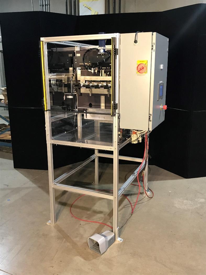
To solve the client’s problem, MJ Engineering developed a machine that can automatically fill up to four syringes at once with the exact amount of fluid desired every time. It reduces or eliminates air bubbles and is faster and more precise than a person or machine filling one syringe at a time. Additionally, it is less complicated and expensive than a fully-automated, high-speed line of equipment.

With MJ Engineering’s machine, an operator can select a pre-programmed “recipe,” which contains information about the size of the syringe and other settings. When ready, the operator loads the bottles and syringes into the machine and presses a foot switch to start the automatic filling process.

MJ Engineering’s oral syringe filling machine can fill up to 400 syringes per hour, doubling the number filled by the client’s most experienced human operator.

In addition to its fast, easy, hands-free operation, the oral syringe filling machine developed by MJ Engineering uses safety light curtains and other methods to protect the operator, and it is made of stainless steel and aluminum for easy cleaning.

To learn more about our engineering and design services, please contact MJ Engineering. For more details about this specific project, refer to the following information.

Project Description

MJ Engineering designed and developed an oral syringe filling machine that saves time and reduces waste for a client in the medical industry.

Capabilities Applied/Processes

  • Designed to fill syringes with liquids of varying viscosities at a volume as low as 0.1 mL
  • Equipped with four, customizable grippers that can handle variable syringe sizes (currently available: 0.5 mL, 1 mL, 3 mL, 6 mL, 12 mL, and 20 mL)
  • Holds up to 999 programmable recipes
  • Adjusts to fit bottles from 3-in. to 7.5-in. in height
  • Fills up to four syringes at once
  • Flips bottle and syringe for filling, eliminating the need for a valve
  • Primes the syringe to reduce or eliminate air bubbles
  • Uses a servo motor with an encoder that goes to a repeatable position for the exact same fill level every time
  • Documentation provided in hardcopy and electronically
  • Training provided for operation and maintenance

Features/Benefits

  • Foot switch/handsfree operation
  • Stainless steel and aluminum parts/easy wipe down
  • Safety light curtains and power lockouts/operator safety
  • Four, customizable grippers/increased speed of operation

More Info

Overall Dimensions
Width: 48 in.
Height: 76 in.
Depth: 46 in.

Electrical Specifications
120 VAC, 1 Phase, 60 Hz, @ 30 Amps

Material Used
Stainless steel and aluminum

Industry for Use
Medical

Delivery Location
Ohio

Product Name
Oral Syringe Filling Machine

Custom Designed Automated Vision Inspection System for the Automotive Manufacturing Industry

An automotive Tier 1 manufacturing client approached MJ Engineering to design and install a custom automated vision based part inspection system. The specific need was to verify that each model is assembled in the correct orientation. The inspection system allows the operator to place a part for inspection upon completing the previous task. The inspection system has a color touch screen operator interface panel for selecting the model to be run and to display pass fail status of the inspection

The vision system is programmed to look for specific characteristics. The system verifies these characteristics are present where they belong and also verify none are present where they don’t. By doing so it is capable of providing 100% verification of the specified characteristics. Each passing part is automatically marked with a quick dry ink for quality tracking purposes.

The customer had been using manual inspection of each part which was very time consuming and also made it difficult to maintain the zero error requirements their customer requires.

Project Description

This automated vision based inspection station verifies the correct assembly of every part manufactured.

Capabilities Applied/Processes

Cell Design

  • Conception of cell that meets unique production requirements.
  • Create SolidWorks© 3D models of cell concept
  • Vision and lighting application concept and testing

Installation

Start-Up

Operator and Maintenance Training

Features/Benefits

Features

  • Utilizes Teledyne Dalsa BOA color vision/li>
  • Portable Cell/li>
  • Provides visual and audible feedback on each part inspected./li>
  • Capable of 30+ individual inspections per part./li>
  • Multiple part types can be programmed and inspected.

Benefits

  • By utilizing a color vision system and the correct lighting for the application it is able to compensate for color and finish variances that are not critical to the part quality test./li>
  • Multiple parts can be programmed and accessed directly by the integrated operator HMI./li>
  • Easily modified to meet new product requirements.

More Info

Overall Cell Dimensions
Table top unit: 39” High x 39” Wide x 39” Deep

Pattern Size Capabilities
50mm high by 300mm wide

Tightest Tolerances
1mm

Material Used
Glass beads

In Process Testing Performed
Samples of all models were provided for initial concept testing

Industry for Use
Automotive

Delivery Location
Ohio

Standards Met
Customer supplied part models

Product Name
Vision Based Automated Inspection System

Integration of Diesel Motor within a Shuttle Car for the Mining Industry

MJ Engineering was tasked with integrating a diesel motor and electric generator in place of a battery pack or cable reel of a mining shuttle car. The customer, who provided a specific set of specifications, needed the diesel motor packaged within the shuttle car’s existing 55 ¾” x 68″ x 32 ¾” reel compartment. We also faced the added challenge of having to ensure that the new motor/generator system was easy to maintain in the harsh and unforgiving mine environment.

To accomplish these tasks, MJ Engineering used a number of different design and engineering processes. We first designed a proper motor/generator mounting frame. Using the natural frequency of the motor/generator we were able to determine which frequencies to avoid so we could design the most stable mounting frame. Then we focused on designing a drive system linking the motor to the generator. Utilizing our outstanding design team we were able to eliminate the need for a battery pack or cable reel within the mining shuttle car. After all this work was completed, MJ Engineering was able to supply the client with 3D CAD models and CAD drawings of the final design.

To learn more about our outstanding design work on this project please contact MJ Engineering or see below for details.

Project Description

MJ Engineering was tasked with integrating a Diesel Motor and an Electric Generator in a mining Shuttle car.

Capabilities Applied/Processes

Design/Engineering

  • Design Concept for Various Motor/Generator Mounting Frames
  • Designed drive system linking Motor to Generator
  • Used the Natural Frequency of Motor/Generator to Determine the Natural Frequency to Avoid When Designing Mounting Frame
  • Created SolidWorks and Solid Edge 3D CAD Models & CAD Drawings of Final Design for Manufacturing

Features/Benefits

Process Requirements

  • Package Motor/Generator within Existing Reel Compartment
  • Ensure it is Easy to Maintain in a Mine environment.
  • Use Motor/Generator System Provided by Client

Benefits

  • Eliminates the need for a Cable

More Info

Overall Dimensions
Car: 352″long x 108″ wide x 93 ½” high Motor/Generator Compartment: 55 ¾ wide x 68 high x 32 ¾” deep

Material Used
Steel plate and tubing

Industry for Use
Mining
Mineral

Delivery Location
Canada

Standards Met
Customer supplied specifications

Product Name
Integration of Diesel Motor/Electric Generator into Mining Car

Custom Designed Fiberglass Processing Robotic Cell for the Truck Industry

Working with a fiberglass processing client located in Ohio, MJ Engineering designed this robotic cell for a custom manufacturing application. Starting with client specifications, we generated concepts for cell design, finally creating a 3D model in SolidWorks for the finished prototype design. Using integrated robot simulation software from FANUC, we carried out a number of time study simulations to ensure that customer requirements would be met.

Design elements of the fiberglass processing robotic cell include a FANUC M20iA 6 axis robot that allows for processing of panels up to 30′ long and 4′ wide, and high-speed production capacity, such as three-dimensional fiberglass routing and automated tool changing. Meeting the demanding production requirements set by the customer, including 385 holes drilled and 750 feet of panel processed per hour, we also designed the cell for ±0.125″ positional repeatability in all processing operations. As required, we also produced electronic documentation as well as training. This particular design allows the customer to adjust the robotic operation for new products, adding to the cell’s efficiency and capability.

Project Description

This Custom Designed Fiberglass Processing Robotic Cell is used to process fiberglass for a manufacturing application.

Capabilities Applied/Processes

Cell Design

  • Conception of Cell that Meets Unique Production Requirements
  • Create SolidWorks 3D Models of Cell Concept
  • Time Study Simulations
    • Utilizing FANUC’s Robot Simulation Software

Installation

Start-Up

Documentation

  • Complete Electronic Documentation Package Provided

Training

  • Operations & Maintenance Training
  • Engineering Training
    • Allows Customer to Train the Robot for New Products As Required

Features/Benefits

Features
Utilizes FANUC M20iA

  • Mounted on a 7th axis Güdel Linear Track
  • Allows for Processing of up to 30′ Long Panels
  • ATI Tool Changer is Utilized

Hi-Speed Production of Fiberglass

  • Routing of Fiberglass Panels in Three Dimensions
  • Over 385 Holes Drilled & 750 Linear Feet of Panel Processed Per Hour
  • Automated Tool Changing-Up to 4 Unique Tools

Benefits

  • Meet High Demanding High Production Requirements
  • Ability to Program Specific Shapes in the Robotic Control System
    • Eliminates the Need for Fixed Custom Made Templates/li>

More Info

Overall Cell Dimensions
Length: Up to 30′
Width: Up to 4′
Height: 6″

Overall Cell Dimensions
Length: 40′
Width: 25′
Height: 6′

Tightest Tolerances
+/-0.125″ Positional Repeatability Over Full Length

Material Processed
Fiberglass

Industry for Use
Truck

Delivery Location
Ohio

Standards Met
Customer supplied specifications

Product Name
Custom Designed Fiberglass Processing Robotic Cell