SpikeEase

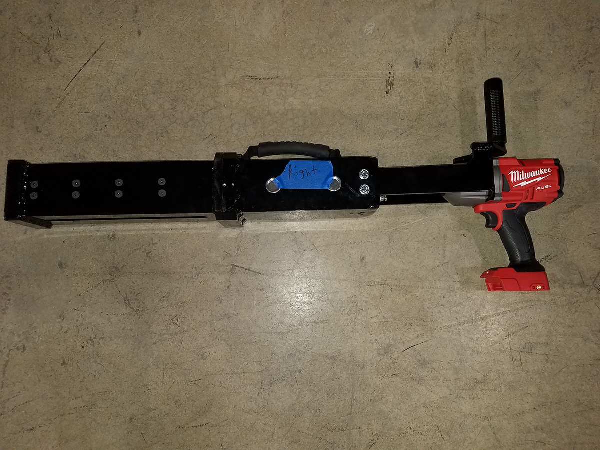
MJ Engineering collaborated with Focused Technologies to develop the award-winning (Best Maintenance of Way Product 2020) and patented SpikeEase railroad spike remover. The SpikeEase project originated as a college senior design project, which MJ Engineering completely redesigned to make stronger, lighter, more powerful, more ergonomic, and easier to use. This product utilizes a customized acme screw and acme nut that when turned by an off-the-shelf impact wrench uses leverage to pull the spike out of the tie. This product is an investment in safety and productivity that pays for itself by increasing production, reducing injuries, and eliminating the need for hydraulic equipment or claw bars. The SpikeEase is designed to be the lightest, easiest, and most eco-friendly spike remover in the world.

According to Focused Technology Solutions, the SpikeEase is the world’s most advanced battery-operated spike remover. Eliminating the need for hydraulic systems means un-tethering employees from service vehicles, heavy hoses, and expensive hydraulic power units.

Goals

  1. Design a battery-powered spike remover
  2. Improve maximum pull force
  3. Reduce the cost of and weight of the SpikeEase.
  4. Improve the ergonomics of using the SpikeEase in the field every day.
  5. Improve the strength and useful life of the SpikeEase

Specifications

  • Weighs in at 30 pounds (not including drill or battery)
  • 3-7 seconds per spike removal
  • A rechargeable battery pack and a commercially available drill
  • Easy to transport anywhere the rail takes you
  • No hydraulic system to risk leaks and environmental hazards.

Custom Designed Robotic Cell for Adhesive Application within the Automotive & Appliance Industry

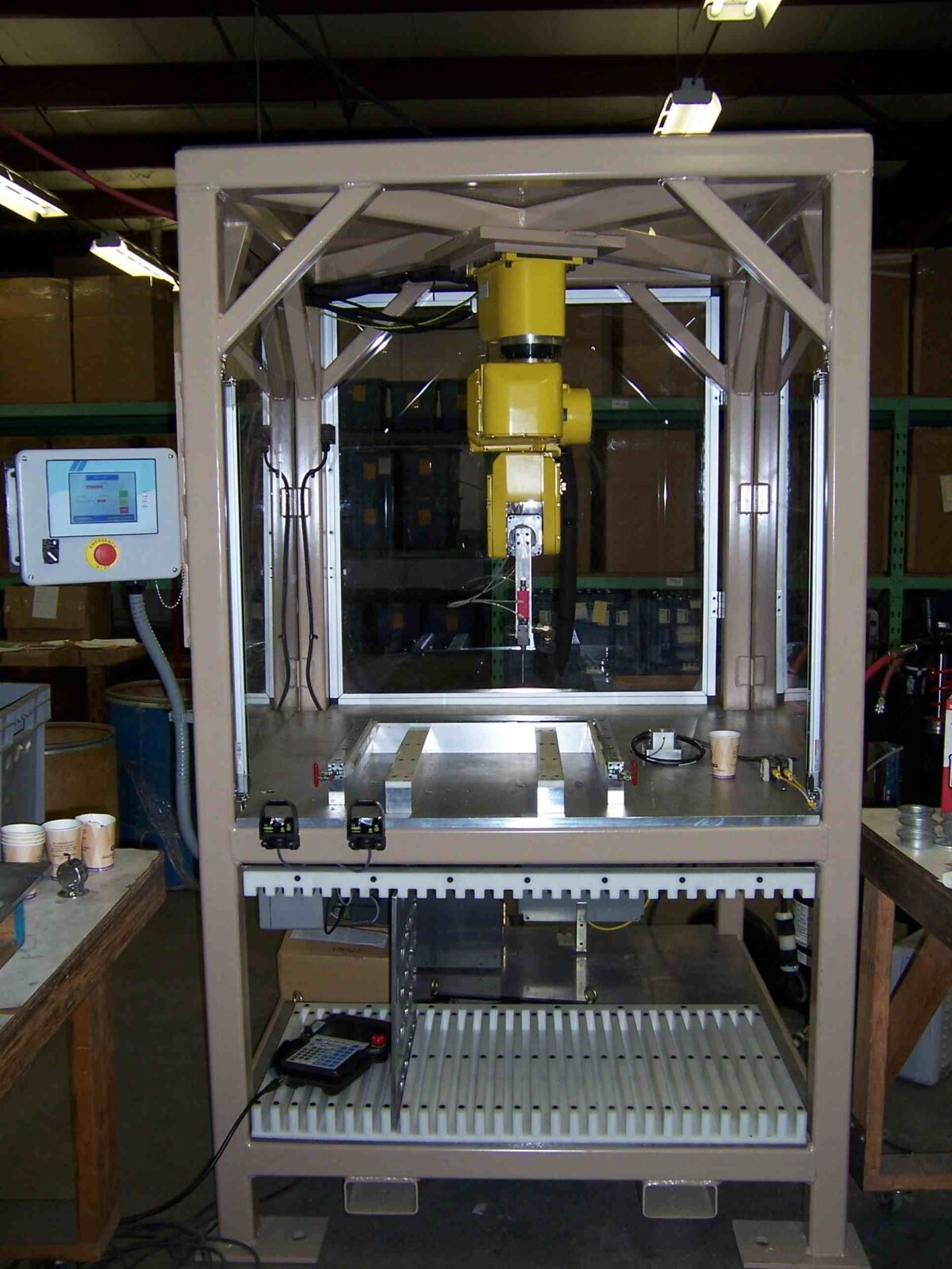
MJ Engineering custom designed and built a portable robotic cell for the automotive and appliance industries. This robotic cell is used for applying a single part epoxy to both automotive and appliance components. Based off a customer supplied 2D, Auto CAD print, we first created Solidworks 3D models of the cell, ensuring that the design met all of our client’s unique product requirements. We also designed the end of arm tooling (EOAT) which possessed built-in temperature control capabilities.

In addition, MJ Engineering also designed and built the epoxy delivery system, which included a number of unique components and features, such as a high-pressure main valve, flexible tubing, and a high-pressure rotary union and metering valve. The cell meets tight tolerances for placement of the adhesive. The cell size is 48-in wide, 48-in deep and 84-in high.

Once assured that our custom designed robotic cell fulfilled all of our customer’s precise product requirements, we then installed this unit in our client’s facility in Coshocton, Ohio. This robotic cell was ready to start up immediately after installation was complete. We also provided our client with comprehensive hard copy and electronic documentation for this unit.

This portable robotic cell contained multiple controlled heating zones for constant viscosity of epoxy delivery, consistent bead size from tray to tray, and changeable epoxy nozzles for specific applications. This cell also allowed for controlled bead of epoxy in tight tolerance patterns on stamped metal parts, providing a speed and consistency that is not capable with traditional manual procedures.

Our robotic cell additionally allowed for storage and easy retrieval of multiple programs, which helps eliminate set-up time for operators. Our automated robotic cell provided our clients higher quality products in reduced production time.

Project Description

This Custom Designed Robotic Cell is used for applying a single part epoxy to automotive & appliance components.

Capabilities Applied/Processes

Cell Design

  • Conception of Cell that Meets Unique Production Requirements
  • Create SolidWorks 3D Models of Cell Concept
  • End of Arm Tooling (EOAT) Design Integrated w/ Temperature Control

Delivery System Design

  • Design of Epoxy Delivery System
  • High Pressure Main Valve
  • Flexible Tubing
  • Hi-Pressure Rotary Union
  • High Pressure Metering Valve

Installation
Start-Up
Documentation Provided in Hardcopy and Electronically
Training Provided for Operations and Maintenance

Features/Benefits

Features
Utilizes FANUC LR Mate 200iB Inverse Mounted
Portable Cell
Applies Controlled Bead of Epoxy in Tight Tolerance Pattern on Stamped Metal Parts
Contains Multiple Controlled Heating Zones
•Creates Constant Viscosity of Epoxy for Delivery
Parts are Manually Loaded into Precision Holding Trays
Provides Consistent Bead Size from Tray to Tray
Changeable Epoxy Nozzles for Specific Applications

Benefits
Vision System Provides Accurate & Repeatable Placement on the Processing Conveyor
Greatly Reduces need for Destructive Testing

More Info

Overall Cell Dimensions
Width: 48″
Height: 84″
Depth: 48″

Pattern Size Capabilities
Ø2″ to ø8″

Tightest Tolerances
Position of Bead: ±.04mm/±.0016″

Material Used
Single Part Epoxy

Industry for Use
Automotive
Appliance

Delivery Location
Coshocton, Ohio

Standards Met
Customer supplied print, 2D Auto CAD Drawing

Product Name
Custom Designed Robotic Cell for Epoxy Application

Finite Element Analysis of an Amusement Park Ride

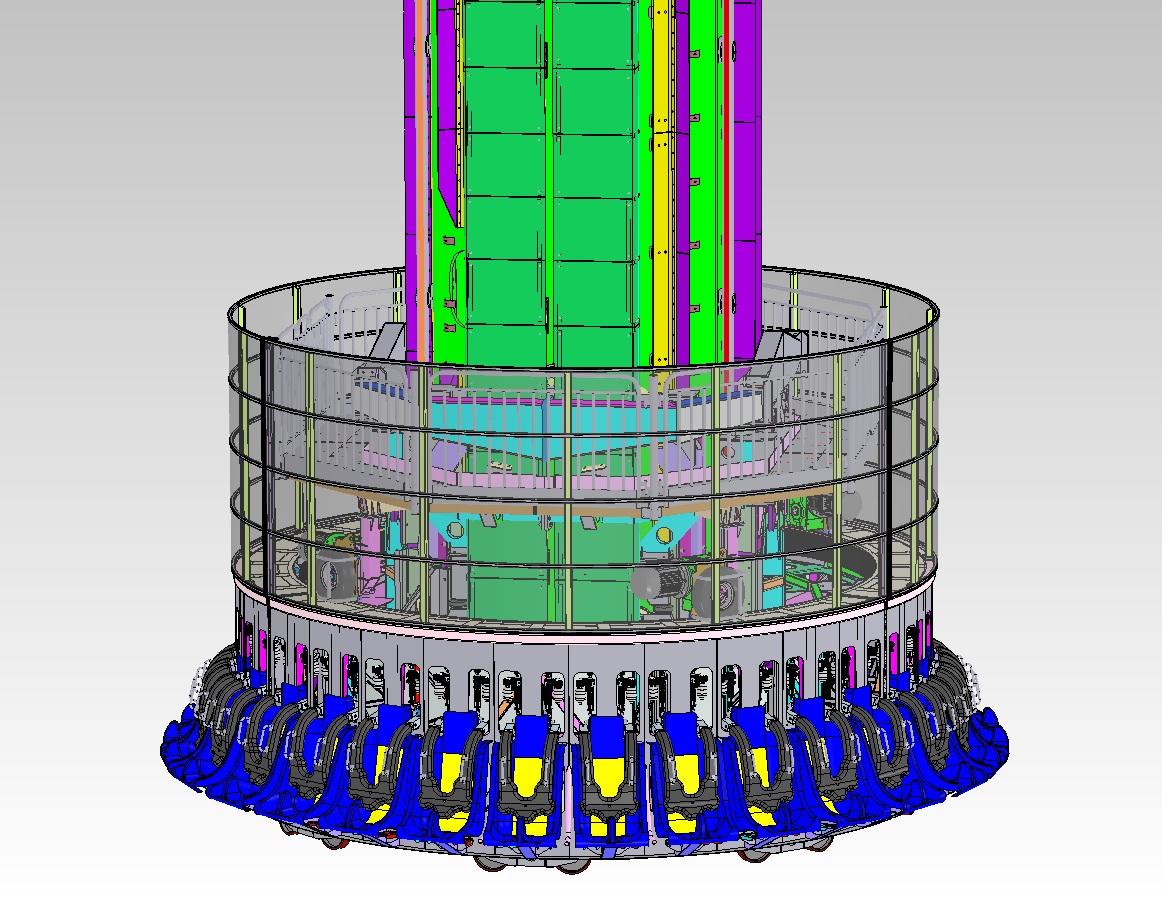
MJ Engineering was retained by a ride manufacturer of an amusement park ride to make sure the ride met US standards for a Virginia-based amusement park. To demonstrate that the structure conformed to local, state and federal regulations, MJ Engineering performed a finite element analysis of the structure under dynamic and static loads. We also helped to establish or guide the design of a number of different control systems including speed and safety controls. To make sure the ride was installed properly, MJ Engineering provided guidance and analysis throughout the entire installation process. Using a variety of specifications (ASTM F2291, AISC 316, AISC M015, ANSI B11.TR3, ANSI B77.1, ASME B15.1, ANSI/AWS D1.1, D14.4, BS 5400-10, SAE T833, ASCE 7) we were able to see that each segment of the ride conformed to the required standards (ASTM, AISC, ANSI, ASME, AWS, BS, SAE, ASCE).

For more information about our finite element analysis of this amusement park ride contact MJ Engineering or see below for details.

Project Description

MJ Engineering structurally reviewed this amusement park ride for Certification within the United States.

Capabilities Applied/Processes

Analysis

  • Performed FEA Analysis of the Structure under dynamic & static loads.
  • Analyzed ride under wind loads & seismic loads to demonstrate the structure conformed to the Local/State/Federal Regulations

Help to establish or guide the design of the following control systems

  • Control Cycle
  • Speed Control (braking)
  • Safety Controls
  • Operator Feedback

Provide Guidance and Analysis to the Customer During Installation
Confirm The Ride Conforms to Amusement Park Standards when Installed

Process Requirements

Specifications that were applied to various segments of the ride:

  • ASTM F2291
  • AISC 316
  • AISC M015
  • ANSI B11.TR3
  • ANSI B77.1
  • ASME B15.1
  • ANSI/AWS D1.1, D14.4
  • BS 5400-10
  • SAE T833
  • ASCE 7

More Info

Industry for Use
Amusement Park

Delivery Location
Virginia

Standards Met
ASTM
AISC
ANSI
ASME
AWS
BS
SAE
ASCE

Product Name
Finite Element Analysis of Amusement Park Ride

Machine Design of Custom Steel Pipe Handling System for the Manufacturing Industry

A manufacturing client approached MJ Engineering to design a custom steel pipe handling system. Using the latest in SolidWorks 3D CAD software, we were able to design both the needed machinery and a master control system.

The custom designed machinery is capable of loading and unloading raw pipe lengths into a CNC threading and cutting cell. We created a handling system that is able to cingulate stock pipe from an accumulation hopper, convey pipe from the output side and sense pipe length and sort it into the correct bin on the discharge end.

To make the machine even more user-friendly, MJ Engineering designed a master PLC system that not only controls movement of the pipe into and out of the CNC cell but also has a touch screen HMI that allows easy operator access and troubleshooting.

We supported the client by offering full assembly and installation of both the steel pipe handling system and the PLC.

For more information on this design project please contact MJ Engineering or see below for details.

Project Description

MJ Engineering designed this machinery to load and unload a pipe into a CNC threading and cutting cell.

Capabilities Applied/Processes

Design/Engineering

  • Design Machine in SolidWorks 3D CAD
  • Design the Control System

Assembly

  • Assemble the Handling System
  • PLC Programming
  • Electrical Enclosure Wiring
  • Machine Wiring

Installation

  • Install Handling System
  • Final Assembly
  • Final Wiring Connection
  • Machine Leveling
  • Securing Machine to Floor
  • Installation Programming

Features/Benefits

Features
Loading equipment that was provided by MJ, which loads raw pipe lengths into the CNC cell. Individual pipes are cingulated onto rollers that convey pipe into the cutting cell.
MJ provided a master PLC system that controls movement of the pipe into and out of the CNC cell. This system has a touch screen HMI that allows easy operator access and troubleshooting.
The CNC cutting/threading machine can produce various lengths.
MJ provided a discharge / sortation conveying system that is capable of identifying individual pipe sections by length and delivering them to the correct bin.

Benefits
Manufacturer was Able to Reduce Manual Operation of the Cutting/Tapping Cell

More Info

Process Requirements
Ability to Cingulate Stock Pipe from An Accumulation Hopper
Feed Pipe into Cutting Cell Using Control Signals from PLC
Convey Pipe from the Output Side
Sense Pipe Length and Sort Into Correct Bin

Overall Cell Dimensions
Length: 42′
Width: 4′
Height: 5′

Material Used
Processes Steel Piping

Industry for Use
Pipe Manufacturing

Delivery Location
Ohio

Standards Met
Customer supplied specifications

Product Name
Design of Steel Pipe Handling System

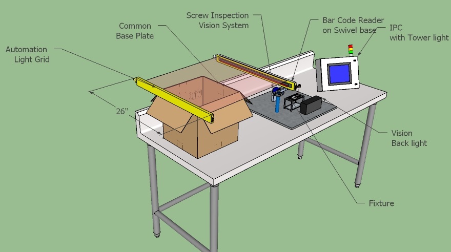
Custom Designed Automated Vision Inspection and Data Logging System for the Automotive Manufacturing Industry

An automotive Tier 1 manufacturing client approached MJ Engineering to design and install a quality system for the purpose of logging data and images from assemblies to provide product traceability. The system uses a 2D reader to read the unique serial identifier and then record the associated assembly data.

One part of the assembly process requires installing screws to specified torque requirements, the next stage is an automated vision based part inspection that checks to make sure the system is assembled correctly. Both the torque data and the vision image are logged to permanent files.

If the torque reading does not fall within tolerance or the vision inspection testing fails the part is not allowed to be packaged and an alarm will sound if an attempt is made to package failed parts.

Project Description

This automated Quality system reads and logs; 2D datamatrix codes, torque values and vision inspection pass/fail criteria.

Capabilities Applied/Processes

Station Design

  • Create custom application software to preform logic and logging functions
  • Create SolidWorks 3D Models of Station Concept
  • Vision and lighting application concept and testing

Installation
Start-Up
Operator and Maintenance training

Features/Benefits

Features
Utilizes SICK© Inspector camera and SICK© Lector 2D reader
A PRODFACE© Industrial PC / HMI is used for operator interface, data logging and logic control
Portable Cell
Provides visual and audible feedback on each part inspected.

Benefits
By utilizing this custom quality control station the customer was able to meet their customers’ quality control standards.
This system virtually eliminates the possibility of shipping incomplete and / or incorrectly assembled parts.
Easily modified to meet new product requirements.

More Info

Overall Cell Dimensions
Table top unit: 36″ High x 48″ Wide x 24″ Deep

Pattern Size Capabilities
1.5″ High x 4″ Wide

Tightest Tolerances
0.05 inch

Material Used
None

In Process Testing Performed
Samples of all models were provided for initial concept testing

Industry for Use
Automotive

Delivery Location
Ohio

Standards Met
Customer supplied quality requirements

Product Name
Automated Vision Inspection and Data Logging System