Robots enhance production of subassemblies

MJ Engineering used its expertise in robotic systems integration to help a client replace old, worn out capital equipment.

A company called on the experts at MJ Engineering to replace an old system that required constant maintenance and no longer met modern safety standards for mechanical equipment. The antiquated system used a fixed, mechanical assembly with cylinders and slides to put together components. MJ Engineering recognized right away that replacing the old mechanical system with a new robotic one would greatly increase its speed, capability, and reliability.

MJ Engineering and Robots to the Rescue

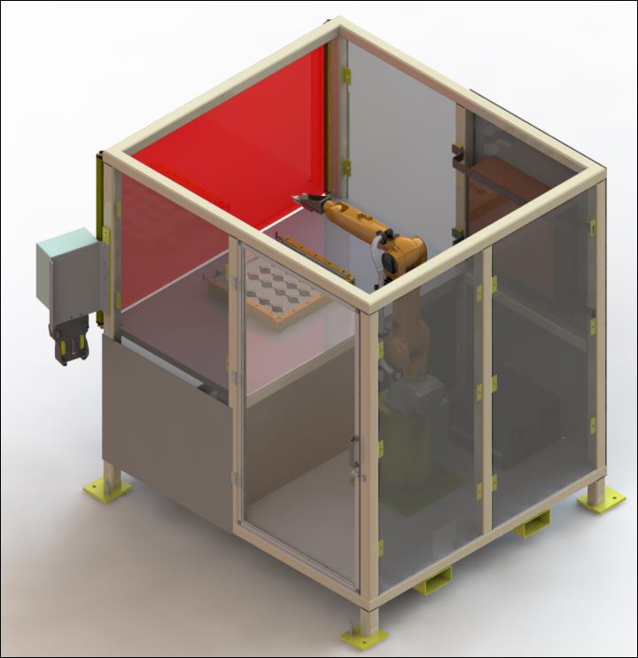
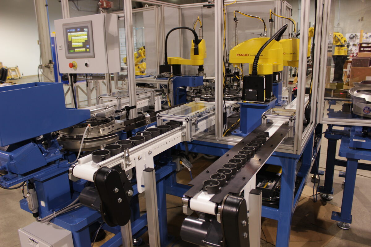
MJ Engineering created a new, safer, faster, and fully-automated system that includes three FANUC high-speed industrial robots. The robots use line tracking and vision guidance to accurately and quickly put together five–piece subassemblies.

Subassembly Components

Each subassembly consists of five reinforced plastic components:

  • Base<
  • Roller
  • Divider
  • Piston
  • Top plate

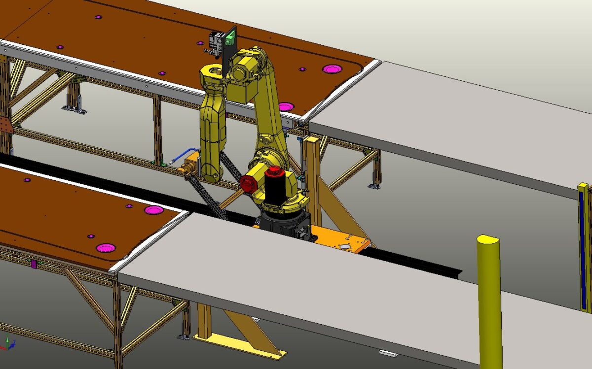
>Robotic vision systems enable the robots to pick parts from the conveyors — in any orientation — place them precisely where they need to go.

Robots at Work

The system MJ Engineering created works like this:

  1. A human operator places a base on the conveyor.
  2. Robot 1 uses a robotic vision system to pick the base off the conveyor and place it into a nest on a turntable.
  3. Robot 1 then picks a roller from a bowl feeder escarpment and places it onto the base.
  4. Robot 2 places the divider (fed by bowl) and the piston (fed by conveyor) onto the base and roller.
  5. An alignment device orients the subassembly to put the piston in the proper position.
  6. Robot 3 takes the top plate from the conveyor (fed into the cell by a neighboring cell), aligns a plastic piece, and places the top plate onto the subassembly.
  7. A servo-driven actuator presses the subassembly shut and blows air into it to verify that the unit rotates, meaning the subassembly is a success.

The whole process takes approximately less than 10 seconds!

Human Machine Interface

While the robots are putting together the subassemblies, an operator can monitor the system using a human machine interface (HMI) mounted to the cell. The operator can use the HMI to correct faults or perform emergency stops and safety resets as needed. The main screen displays a picture of the dial table. Onscreen indicators provide the status of the machine as it operates. When a fault occurs, indicated by a flashing red light, the operator can access a more detailed screen that shows what is happening and where the fault is located. For maintenance and testing, the HMI also includes a password-protected screen with a button for every manual function of the machine. Supervisors can also use this screen to adjust speed, timing, and other settings.

Room to Grow

The cell can be physically adjusted to accommodate larger components.

MJ Engineering Is Your Resource for Robotic Systems

The subassembly cell is just one example of how incorporating robots can improve the safety and speed of an old manufacturing system—and how MJ Engineering can solve your needs with a customized solution. To learn more about our engineering and design services, please contact us at sales@mjengineering.com.

Subassembly Specs

For more details about this specific project, refer to the following table.

Capabilities Applied/Processes

  • An electrical enclosure with an HMI to control the system
  • Documentation provided in electronic and hard copy
  • Training provided for operation and maintenance

Features/Benefits

  • Makes one subassembly in ~9 seconds
  • Conveyors are removable for easy belt replacement

More Info

Overall Dimensions
Width: 6 ft
Height: ~6 ft
Depth: 6 ft

Electrical Specifications
220/480 VAC, 3-Phase, 60 Hz

Material Used
Carbon steel, aluminum, and stainless steel

Robotic Adhesive Cell

Additional Unit Information
Robot Capacity 10kg
Input Voltage 460 VAC
Number of Phases 3
Robot Reach 1101 mm

Project Description

MJ Engineering Analyzed the Canopy Design of a new mine shuttle car, verifying that it conforms to mining standards.

Features/Benefits

Features

  • Robot KUKA® KR 10R1100 sixx
    • KR C4 Compact Controller
    • KUKA smartPAD teach pendant
  • Integrated Touch Screen operator panel
  • Light curtain at operator access
  • Portable Cell
  • Short lead time

Benefits

Safety

  • SICK Light curtains
  • Door Interlocks

Reliability and Efficiency

  • Allows speed and consistency that is not capable with manual procedures
  • Increased production rates
  • Eliminates setup time for operator
  • Control System allows for storage and easy retrieval of multiple programs
  • Easy access for maintenance

Portable

  • Can be moved by forklift
  • Store additional fixtures

Options

  • Adhesive delivery system
  • Temperature control system
  • Size – the overall cell and fixture bed can be adjusted to meet specific needs
  • Robot – the robot model and manufacture can be changed to fit specific requirements
  • Turntable fixture mounting – allows simultaneous robotic application and operator load/un-load
  • Integrated Vision Inspection/Guidance

Custom Designed Fiberglass Processing Robotic Cell for the Truck Industry

Working with a fiberglass processing client located in Ohio, MJ Engineering designed this robotic cell for a custom manufacturing application. Starting with client specifications, we generated concepts for cell design, finally creating a 3D model in SolidWorks for the finished prototype design. Using integrated robot simulation software from FANUC, we carried out a number of time study simulations to ensure that customer requirements would be met.

Design elements of the fiberglass processing robotic cell include a FANUC M20iA 6 axis robot that allows for processing of panels up to 30′ long and 4′ wide, and high-speed production capacity, such as three-dimensional fiberglass routing and automated tool changing. Meeting the demanding production requirements set by the customer, including 385 holes drilled and 750 feet of panel processed per hour, we also designed the cell for ±0.125″ positional repeatability in all processing operations. As required, we also produced electronic documentation as well as training. This particular design allows the customer to adjust the robotic operation for new products, adding to the cell’s efficiency and capability.

Project Description

This Custom Designed Fiberglass Processing Robotic Cell is used to process fiberglass for a manufacturing application.

Capabilities Applied/Processes

Cell Design

  • Conception of Cell that Meets Unique Production Requirements
  • Create SolidWorks 3D Models of Cell Concept
  • Time Study Simulations
    • Utilizing FANUC’s Robot Simulation Software

Installation

Start-Up

Documentation

  • Complete Electronic Documentation Package Provided

Training

  • Operations & Maintenance Training
  • Engineering Training
    • Allows Customer to Train the Robot for New Products As Required

Features/Benefits

Features
Utilizes FANUC M20iA

  • Mounted on a 7th axis Güdel Linear Track
  • Allows for Processing of up to 30′ Long Panels
  • ATI Tool Changer is Utilized

Hi-Speed Production of Fiberglass

  • Routing of Fiberglass Panels in Three Dimensions
  • Over 385 Holes Drilled & 750 Linear Feet of Panel Processed Per Hour
  • Automated Tool Changing-Up to 4 Unique Tools

Benefits

  • Meet High Demanding High Production Requirements
  • Ability to Program Specific Shapes in the Robotic Control System
    • Eliminates the Need for Fixed Custom Made Templates/li>

More Info

Overall Cell Dimensions
Length: Up to 30′
Width: Up to 4′
Height: 6″

Overall Cell Dimensions
Length: 40′
Width: 25′
Height: 6′

Tightest Tolerances
+/-0.125″ Positional Repeatability Over Full Length

Material Processed
Fiberglass

Industry for Use
Truck

Delivery Location
Ohio

Standards Met
Customer supplied specifications

Product Name
Custom Designed Fiberglass Processing Robotic Cell