Collaborative Pick and Place

MJ Engineering and a plastic injection molding company have worked together to develop a cell using a Fanuc CRX-10L to help the molding company improve its current process. The new cell is a collaborative robot cell that performs pick and place operations.

The system utilizes a vacuum end of arm tool that picks the plastic parts and places them in totes. Once placed into totes the robot picks a label and places that on the top rim of the tote. The tote is then ejected out from the station via a sublevel conveyor and the operator is then responsible for placing the label on the tote.

The system has powered conveyors to bring in totes in the center and gravity conveyors to eject full totes. There are right-hand and left-hand parts (mirrors of each other), in order to assist the operator, the output conveyors are separated to help prevent mix-ups of left/right-hand parts. While the cell was originally designed as a collaborative cell, the speed limitations were considerable with everything the client was wanting the cell to do. We
added some guarding and light curtains to allow the cell to run in non-collaborative mode.

Unfortunately, running a collaborative robot in a non-collaborative mode creates significant safety issues and concerns when attempting to meet industry standard safety standards such as RIA. There are various ways to allow this, including safety area scanners, light curtains/fencing, and radar scanners. Collaborative robots are often sold through distributors who don’t understand the safety impacts of integrating a collaborative robot in your facility. They expect you to understand all the requirements and take all the risks.

Come talk to us about your “collaborative” application and get a real perspective on what that means. To see how MJ Engineering can help you, please contact us today!

Depal Cell – Straw Insertion

MJ Engineering has partnered with a commercial cleaning product manufacturer. The result is 2 independent cells. The first is a de-palletizing cell. This particular cell requires an operator who is responsible for putting the pallet of bottles onto a conveyor.Once on the conveyor, the operator walks around and takes off all of the plastic wraps, and uses a foot pedal to move the pallet into the on-deck position. When the robot is ready the pallet is moved into the unloading zone by the conveyor. Once in position, the robot picks the bottles row by row and places them on a smooth top conveyor where they are transferred one by one onto a conveyor that leads to the fill station. When the robot completes the entire layer it rotates the end of the arm tool and picks up the cardboard tier sheet and disposes it down a gravity ramp and moves on to the next layer.

While the robot is working on the current pallet the operator can be preparing the next pallet. Once all bottles/layers have been completed the robot will pull the next pallet into position and the process starts anew.

The 2nd cell is further down the line. The filled bottles come to the straw insertion station where the straws are pushed into the bottlenecks. MJ has a bowl feeder that presents straws 1 by 1 to a rotation table and where collaborative robots pick the straws off of the rotating table and move them into the funnel that aligns the straw with the bottle. Once the straw is dropped we have a pusher that comes down from above and pushes the straw into its locked position and then the bottles are moved out.

This cell features a lot of moving parts. There are multiple 3D printed parts used for all kinds of things of all kinds of different complexities. The dual mirroring collaborative robots feature 3D printed gripper fingers which help grab the straws. The funnels and the centering devices are also 3D printed. The centering device helps us center the bottles and the straw at the same time. Finally, the pushers are also 3D printed and are responsible for setting the straw into the bottle.

Do you have a project that would require complex parts or complex design? We can handle it. Robotic assembly and palletizing are two of the many areas we can help. Contact us today and let us see if we can help you.

Robotic Pack Out

A pharmaceutical company approached MJ Engineering asking for help automating their pack out process. This company had vials randomly stored in totes that needed to be packed into trays. The trays would then be put into boxes and shipped out. The entire process was done by 1 operator who had to organize the vials into trays.

MJ proposed a Fanuc SR-6iA robot to perform a high-speed robotic pack out. The robot featured a gripper end of arm tool to pick up the vials 4 at a time. The vials come to the robot from a bowl feeder which feeds them down a track system that allows the vials to be picked up from the same spot each time. The robot then runs the parts through a machined comb and that straightens the vials up so they could be put in the tray. A conveyor brings the tray around to the operator for packing and shipping.

The robot is able to move an estimated 45,000 vials on a 6.5-hour-long shift. The operator loads the bowl feeder with vials and places empty trays on the conveyor. The high-speed robotic pack out cell comes with a Cognex In-Sight 2000 Vision System to make sure the labels on the vials are placed correctly. The vision system uses a colored ring light to locate the label and verify the orientation.

The cell operates so efficiently that with current production rates the customer only needs to run the cell 3-4 hours a day rather than 3-4 operators 5 days a week.

To see how we can help automate any of your processes give us a call at (614) 891-6111 ext. 110 or email me at jwand@mjengineering.com. We can help with assembly, pack out, depal, and much more in the pharma and medical industries.

Custom Designed Robotic Cell for Adhesive Application within the Automotive & Appliance Industry

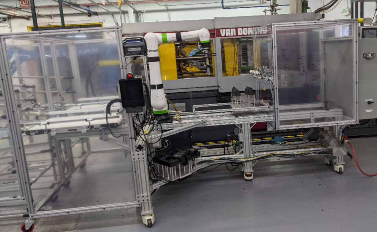
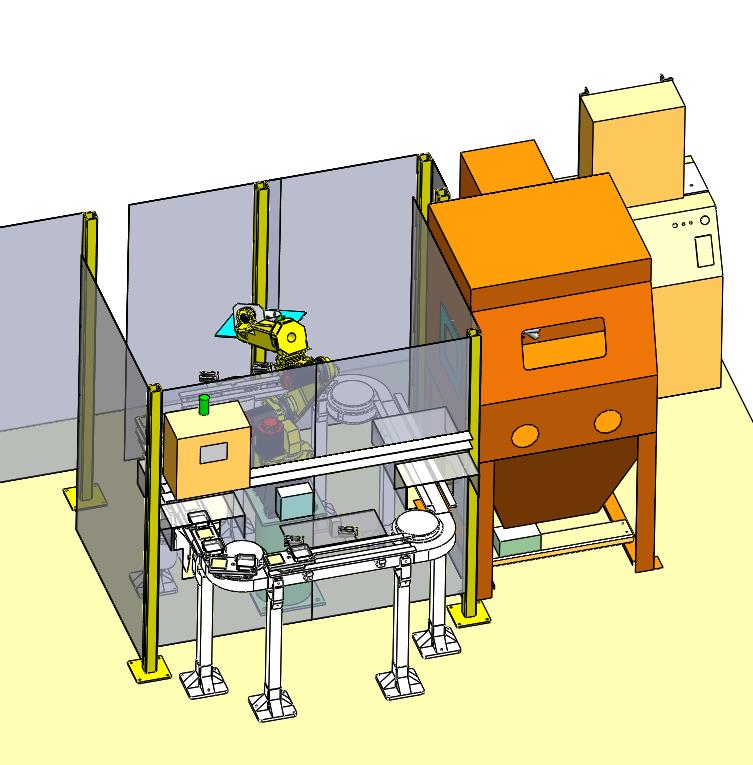
MJ Engineering custom designed and built a portable robotic cell for the automotive and appliance industries. This robotic cell is used for applying a single part epoxy to both automotive and appliance components. Based off a customer supplied 2D, Auto CAD print, we first created Solidworks 3D models of the cell, ensuring that the design met all of our client’s unique product requirements. We also designed the end of arm tooling (EOAT) which possessed built-in temperature control capabilities.

In addition, MJ Engineering also designed and built the epoxy delivery system, which included a number of unique components and features, such as a high-pressure main valve, flexible tubing, and a high-pressure rotary union and metering valve. The cell meets tight tolerances for placement of the adhesive. The cell size is 48-in wide, 48-in deep and 84-in high.

Once assured that our custom designed robotic cell fulfilled all of our customer’s precise product requirements, we then installed this unit in our client’s facility in Coshocton, Ohio. This robotic cell was ready to start up immediately after installation was complete. We also provided our client with comprehensive hard copy and electronic documentation for this unit.

This portable robotic cell contained multiple controlled heating zones for constant viscosity of epoxy delivery, consistent bead size from tray to tray, and changeable epoxy nozzles for specific applications. This cell also allowed for controlled bead of epoxy in tight tolerance patterns on stamped metal parts, providing a speed and consistency that is not capable with traditional manual procedures.

Our robotic cell additionally allowed for storage and easy retrieval of multiple programs, which helps eliminate set-up time for operators. Our automated robotic cell provided our clients higher quality products in reduced production time.

Project Description

This Custom Designed Robotic Cell is used for applying a single part epoxy to automotive & appliance components.

Capabilities Applied/Processes

Cell Design

  • Conception of Cell that Meets Unique Production Requirements
  • Create SolidWorks 3D Models of Cell Concept
  • End of Arm Tooling (EOAT) Design Integrated w/ Temperature Control

Delivery System Design

  • Design of Epoxy Delivery System
  • High Pressure Main Valve
  • Flexible Tubing
  • Hi-Pressure Rotary Union
  • High Pressure Metering Valve

Installation
Start-Up
Documentation Provided in Hardcopy and Electronically
Training Provided for Operations and Maintenance

Features/Benefits

Features
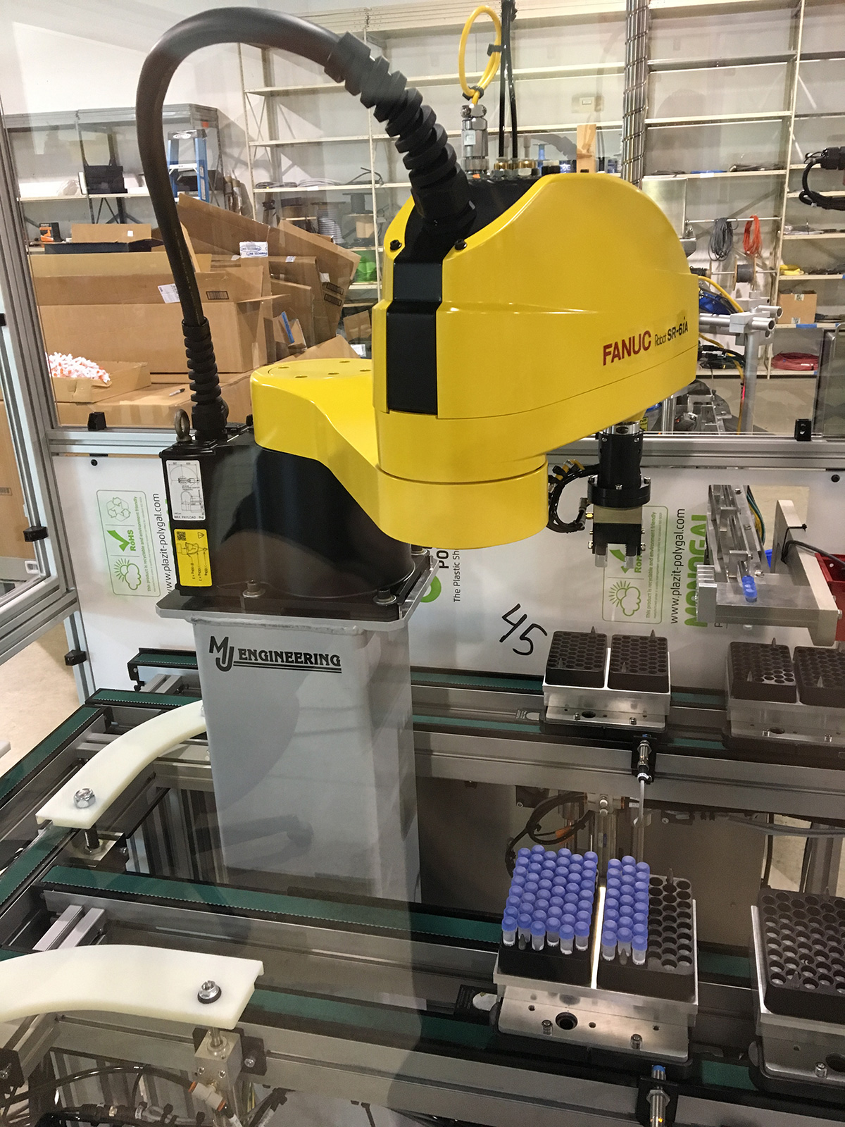
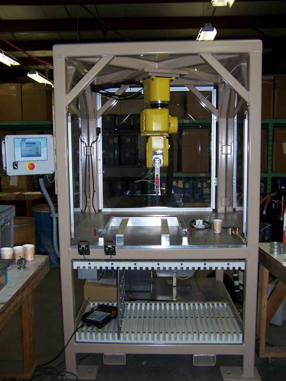
Utilizes FANUC LR Mate 200iB Inverse Mounted
Portable Cell
Applies Controlled Bead of Epoxy in Tight Tolerance Pattern on Stamped Metal Parts
Contains Multiple Controlled Heating Zones
•Creates Constant Viscosity of Epoxy for Delivery
Parts are Manually Loaded into Precision Holding Trays
Provides Consistent Bead Size from Tray to Tray
Changeable Epoxy Nozzles for Specific Applications

Benefits
Vision System Provides Accurate & Repeatable Placement on the Processing Conveyor
Greatly Reduces need for Destructive Testing

More Info

Overall Cell Dimensions
Width: 48″
Height: 84″
Depth: 48″

Pattern Size Capabilities
Ø2″ to ø8″

Tightest Tolerances
Position of Bead: ±.04mm/±.0016″

Material Used
Single Part Epoxy

Industry for Use
Automotive
Appliance

Delivery Location
Coshocton, Ohio

Standards Met
Customer supplied print, 2D Auto CAD Drawing

Product Name
Custom Designed Robotic Cell for Epoxy Application

Custom Designed Robotic Cell for Shot Blasting

A local client approached MJ Engineering to design and install a custom robot cell for the purpose of automatically handling small parts for the purpose of shot blasting one surface in a blast cabinet. The cell incorporates a circular pallet conveyor and a blast cabinet. The shot material and shot process can be modified to allow for different part finish specifications.

The robot uses a custom designed magnetic EOAT (End of Arm Tool) to pick multiple parts from a pallet and present them into a blast cabinet for finishing. The operator loads one of 12 pallets with a tray of unfinished parts then selects the specific processing program from the touch screen operator panel.

The pallets automatically index into and out of the cell as they are processed by the robot and the blast cabinets.

Project Description

This custom designed robotic cell is used for shot blasting a surface finish on very small parts.

Capabilities Applied/Processes

Cell Design

  • Conception of cell that meets unique production requirements.
  • Create SolidWorks© 3D models of cell concept

Tooling Design

  • End Of Arm Tooling (EOAT) Design Integrated w/ a custom designed magnet lifting mechanism.

Installation
Start-Up
Operator and Maintenance Training

Features/Benefits

Features
Utilizes FANUC© M10iB robot with R30iA controller.
Parts are delivered into the cell via the circular pallet conveyor.
Ability to control all blast variables:

  • Duration
  • Presentation (angle and distance)

Benefits
Provides a fully automatic processing cell that requires minimal operator involvement.
Ability to pick variable part sizes for presentation to the blast.
The operator has easy access to the process control via the custom programmed touch screen operator interface panel.

More Info

Overall Cell Dimensions
10 ft. x 7 ft.

Size Capabilities
Part sizes up to 3 in. square

Tightest Tolerances
+/- 0.2mm

Material Used
Shot beads

In Process Testing Performed
Functional runoff (no blast materials) performed prior to delivery

Industry for Use
Specialty manufacturing

Delivery Location
Columbus, Ohio

Standards Met
Customer supplied print, 2D Auto CAD Drawing

Product Name
Custom Designed Robotic Cell for Shot Blasting